
Epiphone Electar Model M (#1260)
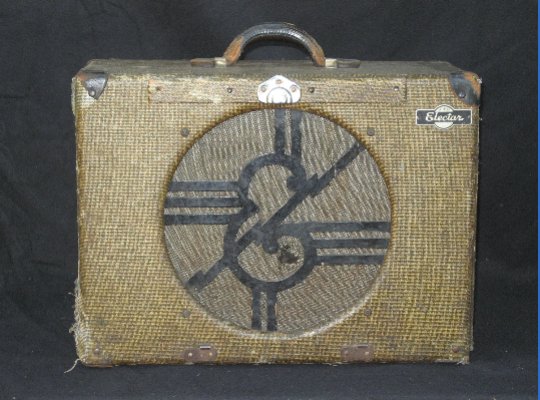
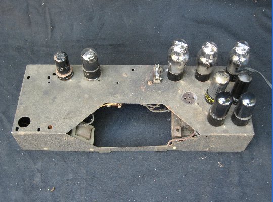
Epiphone Electar Model M #1260
This is the first amp I worked on for Fat Dog at Subway Guitars in Berkeley. Pre-War Epiphone amplifiers were reportedly built by Nate Daniels, later of Danelectro fame. This particular amp was in rough shape---full of mouse droppings, pistachio shells, even some pieces of roofing tile.
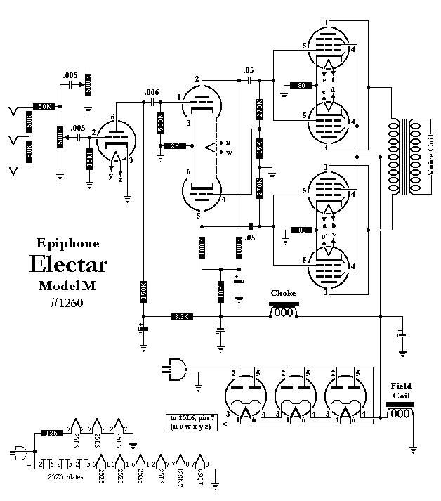
The first thing I do with an old amp is download the pinouts for each of the tubes from Duncan's Amp Pages. Then I draw a schematic. When things start smoking, it helps to have a clearly drawn road map to get you out of trouble. In this case, it was doubly important, because the amp had no power transformer. Like the All American Five table radios, one side of the AC mains was connected directly to the tube heaters and recitifier plates. The other side was soldered to the chassis. The plug was non-polarized. Meaning, every time the amp was plugged in, there was a 50% chance the chassis would have 120 volts on it.
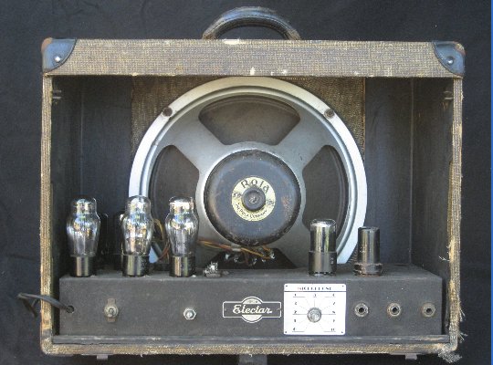
In amps without transformers, the sum of the heater voltages usually equals the mains voltage. Tubes such as 50L6s and 35Z5 are common in these amps as they help to drop the voltage. When I did the math on the Epiphone amp, the values didn't add up. Four 25L6s, three 25Z5s, a 12v and a 6v preamp tube = 193 volts. Hmmmmm.
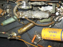
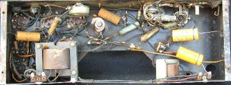
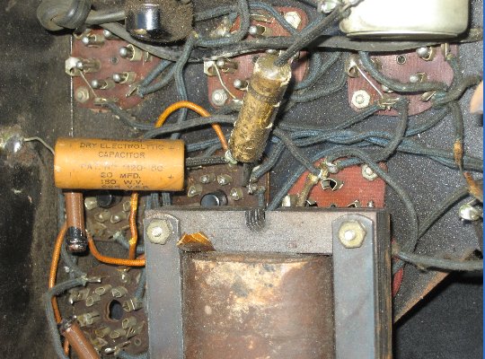
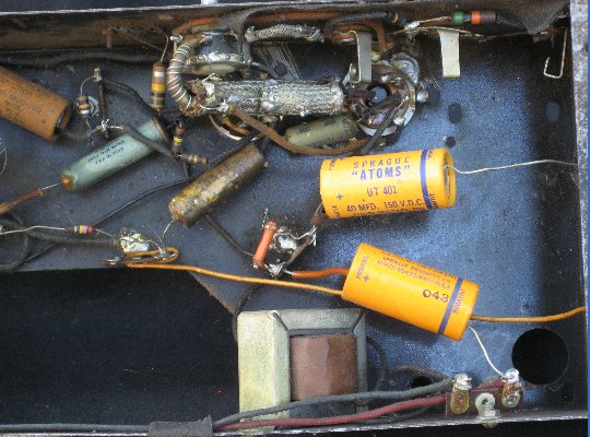
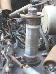
The amp was a mess inside, with two generations of power capacitors, greasy, oozing coupling caps, and an exotic attempt at shielding that looked like a the manifold from a Primus stove. All the wiring was the same color. A wire-wound resistor as big as my thumb was charred on top.
I was meeting my friend, Robb Scott, later that day at the home of his stepfather, Jack Mannarino. Jack is 87 years old. He started his career repairing radios (winding his own coils) and was a radar repairman in the Navy during WW2. Jack had recently fallen down the stairs and had a bandage on his head the size of a yarmulka. Robb, Jack and I polked around the heater wiring and came up with the schema shown above. The amp had 2 parallel heater circuits. One had 3 25Z5s + 1 25L6 + 1 12SN7 + 1 6SC7 (118V). The other circuit had 3 25L6s and a 130 ohm wire-wound dropping resister (shown above).